
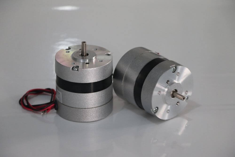
Brushless DC Motor (BLDC) Basics: How They Work and How to Size One
Quick Answer
A BLDC motor is a permanent-magnet synchronous machine whose electronic controller—not brushes—switches the stator current. It runs at 85–93% efficiency versus 75–80% for brushed motors and wears only its bearings, but it cannot start on raw DC: it always needs a driver that senses rotor position, and its temperature limit is set by the magnets, not the insulation.
This page covers what a BLDC motor is, how electronic commutation actually works step by step, the equations that govern torque and speed, and the thermal limits that decide whether a motor survives in the field. It closes with a fully worked sizing example for an AGV drive wheel, including the one arithmetic result that surprises most buyers.
If you already know the theory and simply want hardware, our brushless DC motor range and matching motor controllers cover 22–120 mm frames from 12 V to 72 V.
What Is a Brushless DC Motor?
A brushless DC motor is a permanent-magnet machine that produces continuous rotation by electronically switching current between stator phases in sequence. The name is a little misleading. The bus supply is DC, but the voltage arriving at the windings is a switched AC waveform — trapezoidal in a six-step drive, sinusoidal in a field-oriented drive. Electrically, a BLDC motor is a synchronous AC machine with a DC front end.
Structural Inversion Compared With a Brushed Motor
The defining change is that the two halves of a brushed DC motor swap places:
- Brushed motor: permanent magnets on the stationary housing, current-carrying windings on the rotor. Current reaches the spinning windings through carbon brushes pressing on a segmented commutator.

- BLDC motor: permanent magnets on the rotor, windings on the stationary stator. No sliding contact is required at all.


That inversion drives every practical advantage. Copper loss is the dominant heat source in a small motor, and in a BLDC design it is generated in the stator — bolted directly to the housing, with a short conduction path to ambient. In a brushed motor the same heat is generated in the rotor, where the only escape route is radiation across the air gap. This is why a BLDC motor of a given frame size carries a substantially higher continuous rating than its brushed equivalent, and why the difference widens as frames get smaller.
Core Components
- Stator — laminated silicon-steel core with three-phase copper windings in star (wye) or delta. Lamination grade sets eddy-current loss; slot fill sets copper loss.
- Rotor — permanent magnets, usually sintered NdFeB, either surface-mounted (SPM) or buried in the iron (IPM). Magnet grade sets the temperature ceiling for the whole machine.
- Position feedback — three Hall-effect sensors at 120° electrical spacing, or a sensorless back-EMF observer, or an encoder/resolver for servo-grade control.
- Driver / ESC — a three-phase inverter of six MOSFETs or IGBTs plus the control logic that decides switching order and PWM duty.
- Bearings — the only wearing part left, and therefore the component that now defines service life.
BLDC, PMSM and Stepper — Where the Boundaries Actually Are
These three families share hardware and are frequently confused. The distinction lives in the back-EMF waveform and how the drive exploits it, not in the nameplate.
| Characteristic | Brushed DC | BLDC | PMSM | Stepper |
|---|---|---|---|---|
| Commutation | Mechanical | Electronic, trapezoidal | Electronic, sinusoidal | Electronic, open loop |
| Back-EMF shape | n/a | Trapezoidal | Sinusoidal | Sinusoidal, many poles |
| Typical efficiency | 75–80% | 85–93% | 88–95% | 40–70% |
| Torque ripple | Moderate | ~14% (six-step) | <3% (FOC) | High, cogging-dominated |
| Position feedback | Not required | Hall or sensorless | Encoder/resolver | None (loses steps) |
| Holding torque at zero speed | Poor | Poor without encoder | Good with encoder | Excellent |
| Wear parts | Brushes, commutator | Bearings only | Bearings only | Bearings only |
The practical rule: a BLDC motor driven by a field-oriented controller is a PMSM in everything but the back-EMF waveform, and a well-designed trapezoidal machine run under FOC still gains most of the ripple benefit. The label on the box matters far less than the control strategy you pair with it.
How a BLDC Motor Works, Step by Step
Rotation requires the stator field to stay ahead of the rotor magnets at all times. Because the stator field is created by whichever windings are energised, and the rotor moves continuously, the drive must keep re-selecting windings based on where the rotor is right now. That closed loop is the whole of BLDC operation.
Step 1 — Determine Rotor Position
Three Hall-effect sensors mounted in the stator report the polarity of the rotor magnet passing each one. Their three binary outputs produce six valid states per electrical revolution (000 and 111 are fault codes), giving position to within 60° electrical. Sensorless drives instead measure the back-EMF induced in the one phase that is currently unenergised and detect its zero crossing.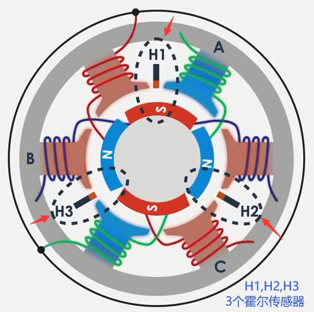
Step 2 — Select the Winding Pair
The controller maps the position state onto a commutation table. In six-step commutation two of the three phases conduct at any moment and the third floats. The sequence AB → AC → BC → BA → CA → CB repeats once per electrical revolution.
Step 3 — Switch the Inverter
Six power switches, arranged as three half-bridges, route bus current through the selected pair. One phase is pulled to the positive rail, one to ground, and the third is left tri-stated. Star connection is what makes this economical: three wires instead of six, with the return path for one phase provided by another phase.
Step 4 — Produce Torque
Current in the energised windings creates a stator field roughly 90° electrical ahead of the rotor field. Like poles repel and opposite poles attract, so the rotor is pulled toward alignment. Torque is proportional to current through the torque constant:
T = Kt × I where T is in N·m, Kt in N·m/A, I in amperes
Step 5 — Advance Before Alignment
The controller must switch to the next state before the rotor reaches alignment, otherwise torque collapses to zero at the alignment point. Switching too early also weakens torque; switching too late increases ripple and audible noise. Correct timing is what separates a motor that hits its datasheet numbers from one that runs hot and loud on the same hardware.
Step 6 — Regulate Magnitude with PWM
Commutation decides which windings conduct; pulse-width modulation decides how much current flows. PWM frequency is normally set between 16 and 20 kHz — above human hearing, but low enough that switching losses in the MOSFETs stay manageable.
Control Strategies Compared
| Method | Position resolution | Torque ripple | Controller cost | Best suited to |
|---|---|---|---|---|
| Six-step / trapezoidal | 60° electrical | ~14% | Lowest | Fans, pumps, constant-speed loads |
| Sinusoidal (SVPWM) | Continuous | 3–6% | Medium | Noise-sensitive, moderate dynamics |
| Field-oriented control (FOC) | Continuous, vector | <3% | Highest | Servos, robotics, traction, wide speed range |
Sinusoidal control regulates the voltage vector and only indirectly controls current magnitude. FOC goes further: it transforms phase currents into a rotating reference frame and regulates the torque-producing component and the flux component independently, holding the stator field at 90° to the rotor field across the entire speed range. That is what delivers maximum torque per amp.
Where the TMC4671 Fits
Historically this article referenced the TMC4671, a fully integrated FOC servo controller originally from Trinamic and now part of Analog Devices. It implements torque, velocity and position control entirely in hardware, with integrated ADCs and position-sensor interfaces, at current-loop update rates up to 100 kHz, and it will drive BLDC, PMSM, two-phase stepper, brushed DC and voice-coil loads.
It is worth knowing about, but it is one option among many — comparable hardware-FOC parts are available from ST, TI and Infineon, and most volume BLDC products use a microcontroller running FOC in firmware instead. Controller choice should follow from the current, bandwidth and feedback the application needs, not from a part number. Our own 20 A 48 V BLDC controller covers 200–400 W applications, and the controller overview lists the rest of the range.
Sensored Versus Sensorless
| Aspect | Hall sensored | Sensorless (back-EMF) |
|---|---|---|
| Starting torque | Full torque from standstill | Open-loop ramp; weak and uncertain |
| Minimum usable speed | Zero | Typically 5–10% of rated |
| Wiring | 3 power + 5 signal conductors | 3 power conductors only |
| High-temperature limit | Hall ICs typically 125–150°C | No sensor to fail |
| Failure mode | Sensor or cable fault stops the motor | Loss of sync under sudden load step |
| Best suited to | AGVs, actuators, anything starting under load | Fans, pumps, compressors, sealed units |
The decision is usually settled by one question: does the motor have to produce torque at or near zero speed? If yes, use Hall sensors or an encoder. A conveyor that starts loaded, a hoist, or an AGV on a ramp will all defeat a sensorless startup ramp.
Engineering Data: Constants, Efficiency and Thermal Limits
The Four Equations That Matter
Almost every BLDC sizing decision reduces to these relationships.
| Quantity | Equation | What it tells you |
|---|---|---|
| Torque | T = Kt · I | Current needed for a given torque |
| Back-EMF | E = Ke · ω | Voltage the motor generates, hence top speed |
| Kv conversion | Kt [N·m/A] = 9.5493 / Kv [rpm/V] | Translates a hobby-style Kv rating into engineering units |
| Motor constant | Km = Kt / √R | Torque per square root of watt dissipated — the true measure of motor quality |
Two facts here trip up almost everyone. First, in SI units Kt [N·m/A] and Ke [V·s/rad] are numerically identical — they are the same physical constant expressed from the mechanical and electrical sides. Second, Kv is inversely proportional to Kt, so a higher Kv number means less torque per amp, not more. A 1000 Kv motor produces 0.00955 N·m/A; a 100 Kv motor of the same frame produces 0.0955 N·m/A, ten times as much.
For the load-side torque arithmetic that feeds into these equations, see how to calculate motor torque.
Why Kv Does Not Determine Efficiency
This is the single most common misconception in BLDC specification, and it is worth proving rather than asserting.
Take one frame size with a fixed slot area and fixed copper fill. Rewinding it with a different number of turns N changes two things together:
- Kt is proportional to N (more turns, more flux linkage per amp)
- R is proportional to N² (more turns of proportionally thinner wire)
Now compute copper loss for a fixed output torque T:
I = T / Kt  →  I ∝ 1/N

Pcu = I²R ∝ (1/N²) · N² = constant
Copper loss is independent of the winding, and therefore independent of Kv. Worked numerically on two 24 V, 60 W candidates delivering the same 0.132 N·m:
| Parameter | Motor A — 300 Kv | Motor B — 1000 Kv |
|---|---|---|
| Kt = 9.5493 / Kv | 0.0318 N·m/A | 0.00955 N·m/A |
| Phase resistance R | 0.500 Ω | 0.045 Ω |
| Current for 0.132 N·m | 4.15 A | 13.8 A |
| Copper loss I²R | 8.6 W | 8.6 W |
| Motor constant Km = Kt/√R | 0.045 N·m/√W | 0.045 N·m/√W |
| Controller continuous rating required | ≥5 A | ≥15 A |
Identical loss, identical motor constant — but the high-Kv option demands a controller rated for three times the current. Since inverter cost, conductor cross-section and switching losses all scale with current, “upgrading to a higher-Kv motor for more speed” triples the drive cost and the wiring burden while delivering exactly zero thermal benefit at the shaft. Kv is a gearing choice on the electrical side, not a performance ratio.
The correct way to compare two BLDC motors on paper is Km, the motor constant. It is winding-independent and captures how much torque the machine produces per unit of heat — which is what actually limits continuous output.
Efficiency by Frame Size
Efficiency is strongly size-dependent because copper loss scales with surface area while output scales with volume. Small motors simply cannot reach large-motor efficiency figures.
| Frame / rating | BLDC peak efficiency | Brushed equivalent | Dominant loss |
|---|---|---|---|
| 22–28 mm, <20 W | 70–80% | 55–65% | Copper |
| 36–42 mm, 20–100 W | 80–87% | 68–75% | Copper + friction |
| 57–80 mm, 100–500 W | 85–91% | 75–80% | Balanced |
| 86–130 mm, 0.5–3 kW | 89–94% | 78–84% | Iron + windage |
Two caveats that catalogue figures rarely spell out. Peak efficiency occurs at roughly 70–80% of rated torque, not at rated torque and not at light load — a motor loafing at 20% load can easily sit 15 points below its headline number. And the quoted figure is almost always motor-only; add 3–8% inverter loss for the system figure. Efficiency classes for variable-speed permanent-magnet machines are defined in IEC TS 60034-30-2, and our motor efficiency class guide explains how the IE bands are assigned.
Thermal Limits: The Magnets, Not the Insulation
This is the BLDC-specific trap that catches engineers coming from brushed or induction machines. Insulation class per IEC 60034-1 sets the winding limit, but the rotor magnets usually give up first.
| Magnet material / grade | Max working temp | Relative cost | Typical use |
|---|---|---|---|
| NdFeB — N (standard) | 80°C | Baseline | Consumer fans, light duty |
| NdFeB — M | 100°C | +10% | General industrial |
| NdFeB — H | 120°C | +20% | Automation, AGV |
| NdFeB — SH | 150°C | +35% | Traction, power tools |
| NdFeB — UH / EH | 180–200°C | +50–80% | EV, engine bay, downhole |
| SmCo | 250–350°C | 3–5× | Aerospace, extreme ambient |
| Ferrite | 250°C (hot) / poor cold | 0.2× | Cost-driven, high ambient |
Read that against the insulation table and the mismatch is obvious:
| Insulation class (IEC 60034-1) | Max winding temp | Permitted rise at 40°C ambient |
|---|---|---|
| Class A | 105°C | 60 K |
| Class E | 120°C | 75 K |
| Class B | 130°C | 80 K |
| Class F | 155°C | 105 K |
| Class H | 180°C | 125 K |
A motor advertised with Class F insulation implies a 155°C winding capability. If it is fitted with standard N-grade NdFeB, the magnets begin to demagnetise irreversibly around 80°C — roughly half the headline number. The winding is fine; the torque constant has permanently dropped and the motor never recovers, even after cooling.
There is also a fully reversible effect you should budget for. NdFeB remanence falls by about 0.12% per °C. Going from a 20°C bench test to a 100°C hot-soak costs roughly 9.6% of Kt, so the drive must push about 10% more current for the same torque — which raises I²R loss by around 21% and heats the motor further. Size the current headroom for the hot condition, not the bench measurement. When output torque falls off after a machine has been running for an hour, this is usually why; see what causes a DC motor to lose torque.
One counterintuitive case worth remembering: ferrite magnets lose remanence as they get colder and can suffer irreversible demagnetisation at low temperature. A ferrite-magnet motor specified for a hot factory may fail during a cold-start test in a winter warehouse.
Best Applications for BLDC Motors
BLDC motors earn their extra controller cost wherever duty cycle is long, maintenance access is poor, or control precision matters. Where a load runs briefly and rarely, a brushed motor is often still the correct commercial answer.

Continuous-Duty Air Movement
Cooling fans, blowers and ventilation sets run thousands of hours a year, so an 85% motor against a 70% motor pays back quickly, and there are no brushes to replace in an inaccessible duct. Silent-PC fans, laptop cooling bases and high-speed blowers are almost universally BLDC. Related: appliance motor applications.
Battery-Powered Tools
Cordless drills, impact wrenches and electric screwdrivers moved to BLDC because runtime per charge is set directly by efficiency, and because electronic control allows clutch behaviour, soft start and precise torque limits in firmware rather than hardware.
AGVs and Mobile Robots
Drive wheels need full torque from standstill, regenerative braking and accurate speed matching between wheels — all of which require closed-loop electronic control. These are normally Hall-sensored or encoder-equipped and geared through a planetary stage. Thermal management is the usual field failure; see AGV motor overheating and how a planetary gearbox works.
Electric Vehicles and Light EV
Hub motors, mid-drives and auxiliary actuators exploit BLDC power density and regeneration. Magnet grade and thermal design dominate the specification. Our EV-grade BLDC motors use SH and UH grades for under-bonnet and traction duty.
Medical and Laboratory Equipment
Infusion pumps, centrifuges, surgical tools and analysers need low EMI, no particulate generation from brush dust, quiet running and long unattended life. Brush arcing alone disqualifies brushed motors from many of these environments.
Pumps and HVAC Plant
High annual running hours make efficiency the primary purchase criterion, and sealed sensorless BLDC designs suit wet or inaccessible installations. Relevant to chilled water and industrial cooling pump drives.
Precision Motion and Robotics
Robot joints, CNC axes and semiconductor handling need low torque ripple and accurate position, which means FOC plus an encoder. Where backlash matters more than torque, the gearbox choice dominates — see harmonic vs planetary gear and precision planetary gearbox applications.
Space-Constrained Actuators
Where axial length is limited, a pancake BLDC with an integrated reducer is often the only fit. See flat BLDC gear motors and micro gearboxes.
How to Select a BLDC Motor: Step-by-Step
Work from the load backwards. Choosing a motor first and then discovering the load is the most expensive sequence available.
Step 1 — Quantify the Load
Establish required output speed, continuous torque, peak torque, and the duty cycle that connects them. For intermittent duty compute RMS torque over the cycle — that, not peak, sets the thermal size.
Step 2 — Decide Direct Drive or Geared
BLDC motors are efficient at high speed and poor at low speed. Below roughly 500 rpm at the load, a gearbox almost always produces a smaller, cheaper, cooler system. See direct drive vs gear motor and, if geared, different types of speed reducers.
Step 3 — Select the Gear Ratio
Divide motor rated speed by required output speed and round to the nearest catalogue ratio. Recheck resulting output speed against the specification. Method detail is on speed reducer motor selection.
Step 4 — Reflect Torque Back to the Motor Shaft
Tmotor = Tload / (i × η). Use a realistic gearbox efficiency: about 0.95 per spur or planetary stage, 0.90 for two stages, and 0.45–0.70 for worm depending on ratio.
Step 5 — Choose Voltage and Kv Together
Required no-load speed divided by available bus voltage gives target Kv, but derate: a loaded motor runs roughly 10–20% below its no-load speed at the same voltage. Then check the resulting current against the controller you can actually afford — as the worked example below shows, this is the constraint that usually binds.
Step 6 — Verify the Thermal Case
Compute copper loss at continuous torque, add iron and friction loss, and check against the motor’s thermal resistance and worst-case ambient. Confirm the magnet grade suits the resulting rotor temperature, not just the insulation class.
Step 7 — Size the Controller on Continuous Current
Match continuous current, peak current, bus voltage and feedback type. Controllers are commonly quoted on peak rating; you need the continuous figure with the intended heatsinking.
Step 8 — Confirm the Mechanical Interface
Shaft diameter, flange pattern, mounting depth, connector type and IP rating. See what a motor flange is. For anything non-standard, our custom motor development route is usually faster than forcing a catalogue part to fit.
Worked Example: AGV Drive Wheel
Specification. 80 kg loaded AGV, two driven wheels, 150 mm polyurethane wheels on sealed concrete, 0.8 m/s target speed, must climb a 5% ramp, 0.5 m/s² acceleration, 24 V battery bus.
1. Force at one wheel (40 kg share, Crr = 0.02):
Rolling   F = 0.02 × 40 × 9.81 = 7.85 N

Grade     F = 40 × 9.81 × 0.05 = 19.62 N

Accel     F = 40 × 0.5 = 20.0 N

Total     F = 47.5 N
2. Wheel torque and speed (r = 0.075 m):
Twheel = 47.5 × 0.075 = 3.56 N·m

nwheel = 0.8 / (π × 0.15) × 60 = 101.9 rpm
3. Gear ratio from a 3,000 rpm BLDC:
i = 3000 / 101.9 = 29.4 → select catalogue 30:1 planetary

Actual output = 3000 / 30 = 100 rpm → 0.785 m/s (1.8% under target, acceptable)
4. Motor torque (two-stage planetary, η = 0.90):
Tmotor = 3.56 / (30 × 0.90) = 0.132 N·m

Pmotor = 0.132 × (3000 × 2π / 60) = 41.5 W
A 60 W frame gives roughly 1.45× margin on the acceleration case, which is appropriate given that acceleration is intermittent while rolling and grade loads are continuous.
5. The Kv decision. Two 24 V, 60 W candidates both deliver 0.132 N·m and, as proved above, both dissipate 8.6 W doing it. The 300 Kv option draws 4.15 A and needs a 5 A controller. The 1000 Kv option draws 13.8 A and needs a 15 A controller with three times the conductor cross-section and a real heatsink.
The result worth flagging: a 60 W motor on a 24 V bus is a 2.5 A-class load if you wind it correctly, and a 14 A-class load if you do not — with identical shaft output and identical motor heating. On this AGV the entire drive-electronics budget is decided by a parameter that has no effect whatsoever on motor performance. Specify Kv from the voltage and speed you have, then compare candidates on Km.
Common Engineering Mistakes
1. Sizing on Peak Torque Instead of RMS Torque
A motor sized for the acceleration peak is typically two frame sizes too large and runs at poor efficiency for most of its life. Compute RMS torque across the duty cycle for the thermal size and check peak only against the demagnetisation and controller current limits.
2. Assuming Insulation Class Sets the Thermal Ceiling
Class F says 155°C. Standard N-grade NdFeB says 80°C. The magnets set the limit, and exceeding it destroys torque permanently rather than gradually. Always ask for the magnet grade, not just the insulation class.
3. Treating a High Kv Number as a Performance Upgrade
Kv is a winding choice, not a quality metric. Higher Kv buys speed per volt and costs torque per amp in exact proportion. Compare motors on Km = Kt/√R instead.
4. Choosing Sensorless for a Load That Starts Under Torque
Sensorless drives ramp open-loop until back-EMF is detectable, typically 5–10% of rated speed. A loaded conveyor, a hoist or an AGV on a ramp will stall or lose sync during that window. If torque is needed at zero speed, fit Hall sensors.
5. Rating the Controller on Peak Current
Controller datasheets lead with peak current, which may be sustainable for only a few seconds. Continuous current at the actual heatsink and ambient is the number that matters. Undersizing here is the most common cause of a system that works on the bench and trips in the cabinet.
6. Ignoring Motor Cable Length and PWM Effects
Long unshielded motor cables radiate at the PWM fundamental and its harmonics, and fast dV/dt edges can stress winding insulation through reflected-wave effects. Use shielded cable bonded at both ends, keep runs short, and do not raise PWM frequency beyond what the application needs.
7. Neglecting Bearing Selection and Alignment
With brushes gone, bearings are the life-limiting component. Misalignment, excessive belt tension or incorrect preload will produce a failure at a few thousand hours in a motor rated for 20,000. SKF’s failure-mode catalogue is the standard diagnostic reference.
BLDC Troubleshooting: Problem, Cause, Solution
| Problem | Probable cause | Solution |
|---|---|---|
| Motor jerks or vibrates but will not turn | Hall-to-phase mapping incorrect | There are six valid phase/Hall permutations; work through them systematically or run the drive’s auto-detect routine |
| Runs in the wrong direction | Phase order or Hall order reversed | Swap any two motor phases and the corresponding two Hall lines |
| Torque falls away after 30–60 minutes of running | Reversible magnet loss at temperature (−0.12%/°C), or irreversible demagnetisation | Measure case temperature; if torque does not return after cooling the magnets are permanently damaged — move to a higher grade |
| Audible whine or growl under load | Six-step commutation ripple, or PWM in the audible band | Raise PWM to 16–20 kHz; move to sinusoidal or FOC to cut ripple below 3% |
| Controller overheats while motor stays cool | Kv too high for the application, so current is high for the required torque | Select a lower-Kv winding at the same Km, or add gear reduction and reduce motor torque |
| Overcurrent trip on every start | No current ramp; full duty applied into a stationary rotor | Enable soft-start with a current-limited ramp; verify inertia is within the drive’s acceleration setting |
| Rough, cogging motion below 10% speed | Sensorless back-EMF too weak to resolve position | Add Hall sensors or an encoder; alternatively use FOC with high-frequency injection |
| Measured efficiency well below datasheet | Operating far from the peak-efficiency point, or comparing motor-only figures against system measurements | Re-gear so continuous load sits at 70–80% of rated torque; add 3–8% for inverter loss when comparing |
| Bearing noise appears after a few thousand hours | Misalignment, excess radial load, contamination or wrong preload | Check coupling alignment and belt tension against the overhung-load limit; refer to SKF bearing failure modes |
| Erratic operation with long motor cables | EMI coupling into Hall lines; reflected-wave voltage stress | Shielded cable bonded both ends, separate signal and power routing, add common-mode chokes |
Frequently Asked Questions
What is the difference between a BLDC motor and a brushed DC motor?
A brushed motor has windings on the rotor and magnets on the housing, with carbon brushes switching current mechanically. A BLDC motor reverses this — magnets on the rotor, windings on the stator — and switches current electronically. The BLDC motor is typically 85–93% efficient against 75–80%, lasts 20,000+ hours instead of 1,000–5,000, generates far less EMI, and rejects heat better because losses occur in the stationary housing. Its disadvantage is that it cannot run without a controller.
Is a BLDC motor the same as a PMSM?
They are closely related permanent-magnet synchronous machines. The formal distinction is the back-EMF waveform: trapezoidal for BLDC, sinusoidal for PMSM. In practice the boundary has blurred, because a trapezoidal machine driven by field-oriented control behaves much like a PMSM. Choose based on the control strategy and required torque smoothness rather than the label.
Do BLDC motors need a controller?
Yes, always. Connecting a BLDC motor directly to a DC supply energises one winding pair and locks the rotor at that position; it will not turn. The controller must know rotor position — via Hall sensors, back-EMF or an encoder — and sequence the phases accordingly. This is why BLDC system cost is higher than the motor price alone suggests.
What does Kv mean on a BLDC motor?
Kv is no-load speed in rpm per volt applied. It is inversely related to the torque constant: Kt [N·m/A] = 9.5493 / Kv [rpm/V]. A high Kv motor spins faster per volt but produces proportionally less torque per amp. Critically, Kv does not affect efficiency — for a given frame, copper loss at a given torque is the same regardless of winding. Compare motors using the motor constant Km = Kt/√R instead.
How long does a BLDC motor last?
With no brushes to wear, life is set by bearings and magnets. Well-specified industrial BLDC motors reach 20,000–50,000 hours. Bearing L10 life under correct load and alignment is normally the governing figure. The main way to shorten it dramatically is thermal: running magnets above their grade limit degrades torque permanently, and every 10°C of extra winding temperature roughly halves insulation life.
Can a BLDC motor run without Hall sensors?
Yes. Sensorless drives detect back-EMF in the unenergised phase to infer rotor position, saving five conductors and removing a failure point. The limitation is at low speed: back-EMF is proportional to speed, so below roughly 5–10% of rated speed it is too weak to resolve. Sensorless suits fans, pumps and compressors that start unloaded; it is a poor choice where full torque is needed from standstill.
What temperature can a BLDC motor withstand?
Two separate limits apply and the lower one governs. Winding insulation follows IEC 60034-1 classes — B at 130°C, F at 155°C, H at 180°C. Rotor magnets are usually stricter: standard NdFeB tops out near 80°C, with H, SH, UH and EH grades reaching 120, 150, 180 and 200°C respectively. Because the magnet limit is frequently below the insulation limit, always confirm the magnet grade when specifying for elevated ambient.
Why Choose Greensky for BLDC Motors
Greensky Power manufactures brushless DC motors, gear motors and matched controllers for OEM customers worldwide. What is relevant to the engineering discussed above:
- Magnet grade specified, not assumed. We state NdFeB grade and working temperature on every quotation, because as shown above the magnet, not the insulation class, usually sets the real thermal ceiling.
- Winding matched to your bus voltage. Rather than pushing a stock Kv, we wind to your supply and target speed so the controller current lands where your drive budget allows. Frames from 22 mm to 120 mm, 12 V to 72 V.
- Motor, gearbox and drive from one source. BLDC motors, gearboxes and controllers engineered together, which removes the interface mismatch that appears when three suppliers each meet their own spec.
- Sensored and sensorless variants of the same frame, so the feedback decision can follow the application instead of the stock list.
- Full type coverage on the gear side — planetary, helical, worm (NMRV), cycloidal and flat BLDC gear motors — so the recommendation follows the calculation.
- Custom shafts, flanges, connectors and ratios through our custom motor development and OEM/ODM programmes, typically faster than adapting a catalogue part.
Send us the load, speed, duty cycle, bus voltage and ambient temperature, and our engineers will return a calculated recommendation with the torque, current and thermal working shown — not just a part number.
Related Technical Resources
- Brushless DC motor range and specifications
- Brushed DC motors — when they are still the right choice
- Motor controllers and drives
- How to calculate motor torque
- How to select a motor for an industrial application
- Motor efficiency class explained
- What is the use of a DC geared motor
- Speed reducer motor selection and calculation
- Different types of speed reducers compared
- Direct drive motor vs gear motor
- Planetary gear motor application fields
- All DC motor technical articles
References and Standards
The efficiency figures, insulation classes, duty definitions and failure modes cited above are drawn from published international standards and manufacturer technical documentation. Magnet temperature coefficients and grade limits reflect sintered NdFeB supplier data; the motor-constant derivation is standard machine theory and is reproducible from the equations given. This page is maintained by the Greensky Power engineering team and reviewed against current standard editions.
- International Electrotechnical Commission. IEC 60034-1:2022 — Rotating electrical machines, Part 1: Rating and performance. https://webstore.iec.ch/en/publication/65446
- International Electrotechnical Commission. IEC TS 60034-30-2 — Efficiency classes of variable speed AC motors (IE-code). https://webstore.iec.ch/publication/30830
- International Electrotechnical Commission. IEC 60034-30-1 — Efficiency classes of line operated AC motors. https://webstore.iec.ch/publication/91195
- American National Standards Institute / NEMA. ANSI/NEMA MG 1 — Motors and Generators. https://webstore.ansi.org/standards/nema/ansinemamg2021
- National Electrical Manufacturers Association. Motors and Generators product section. https://www.nema.org/products/pages/motor-and-generator.aspx
- U.S. Department of Energy. Determining Electric Motor Load and Efficiency. https://www.energy.gov/sites/prod/files/2014/04/f15/10097517.pdf
- International Energy Agency. Electric Motors — Energy System, Industry. https://www.iea.org/energy-system/industry/electric-motors
- SKF. Bearing Failures and Their Causes. https://www.skf.com/group/support/bearing-failures-and-their-causes
- Siemens AG. SIMOTICS Electric Motors — Technical Documentation. https://www.siemens.com/global/en/products/drives/electric-motors.html
- IEEE Xplore. Permanent magnet synchronous and brushless DC motor drives — technical literature. https://ieeexplore.ieee.org/document/6342334
- maxon motor ag. EC Motor Technology — Brushless DC Drive Fundamentals. https://www.maxongroup.com/maxon/view/content/ec-technology
- maxon motor ag. Gear Technology Technical Paper. https://www.maxongroup.com/assets/public/caas/v1/media/112608/data/32bb5bfabd9ce7d852292f275410c997/knowledge-support-support-antriebswissen-kurz-erklaert-gear-download.pdf
- FAULHABER. Brushless DC Motors — Product and Technology Documentation. https://www.faulhaber.com/en/products/brushless-dc-motors/
- FAULHABER. Drive Technology Know-How Library. https://www.faulhaber.com/en/know-how/
- Yaskawa. Technical Downloads and Application Notes. https://www.yaskawa.com/downloads/search-index
- Analog Devices (Trinamic). TMC4671 — Integrated Servo Controller for FOC. https://www.analog.com/en/products/tmc4671.html
