
How Motor Speed Affects Micro Pump Flow Rate
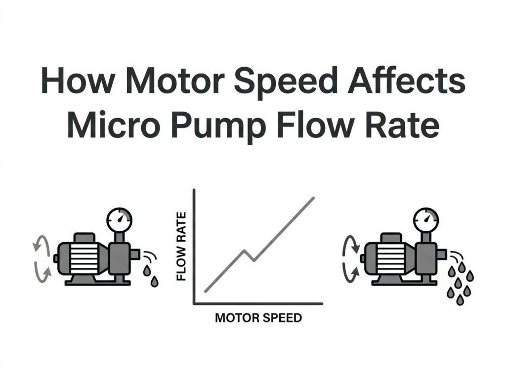
The RPM → displacement → flow chain, and why flow diverges from linearity at the speed extremes.
Quick Answer
A micro gear pump is a positive-displacement device, so its flow is governed by one chain: motor RPM → pump displacement per revolution → flow, expressed as Q ≈ V × RPM. Inside the pump’s valid speed window the relationship is nearly linear, so doubling RPM doubles flow. It breaks down at the edges — at very low RPM internal slip dominates and efficiency collapses, and at very high RPM the inlet cannot fill the gear chambers fast enough, triggering cavitation that caps or even reduces flow. A brushless DC (BLDC) motor with closed-loop speed control keeps the delivered flow tightly proportional to the commanded RPM across the whole operating band.
In this guide
- What Is the Relationship Between Motor Speed and Pump Flow?
- How RPM Translates Into Flow: The Displacement Chain
- RPM vs Flow Rate: Comparison Table
- Engineering Data: Flow Formulas, Efficiency Limits, Speed Windows
- Best Applications for Speed-Controlled Micro Pumps
- How to Select the Right Motor Speed for Your Flow Target
- Common Engineering Mistakes When Sizing by RPM
- Troubleshooting: Flow Problems vs Motor Speed
- Why Choose GreenSky?
- References
- FAQ
What Is the Relationship Between Motor Speed and Pump Flow?
A micro gear pump belongs to the positive-displacement family: every complete revolution of the gear set traps and moves a fixed volume of fluid, the displacement V (in ml/rev or µl/rev). Unlike a centrifugal pump, whose flow depends on pressure and a curved P–Q characteristic, a gear pump’s output is pinned to how fast its shaft turns. The instantaneous flow is therefore decided by the motor, not by the fluid system.
This is the single most useful fact for OEM fluid-system engineers: if you can command the motor speed, you command the flow. The entire job of flow control reduces to controlling RPM. That is why micro-pump performance is almost always described by the equation Q = V × N and why a precise BLDC drive with closed-loop speed control is the cleanest way to deliver a target flow rate. As we cover in motor speed selection for gear pumps, the motor does not just spin the pump — it defines the pump’s flow envelope. The broader RPM-setting methodology we apply to drive motors is summarized in our motor speed and RPM guide.
Two qualifiers matter. First, the displacement V is a fixed geometric property of the pump head (set by gear size, width and tooth count), so flow scales with RPM only if V stays constant — which it does for a given head. Second, real flow is always a little below the ideal value because of internal leakage, so the practical relation is Q_actual = V × N × η_v. The rest of this article is about where that simple chain holds, and where it quietly breaks.
How RPM Translates Into Flow: The Displacement Chain
Follow the chain end to end. It has four physical links, and a failure at any link breaks the proportionality:
- Commanded motor speed. The BLDC driver sets the shaft speed through PWM duty cycle or an analog set-point (typically 100–4,000 RPM for micro pumps).
- Speed delivered to the pump shaft. Direct drive transmits RPM 1:1; a magnetic coupling (used in magnetic gear pumps) transmits it without seals, while a reduction gearbox divides it. The pump sees the post-transmission speed.
- Displacement per revolution. Each turn moves
Vml of fluid. For a Greensky MG-class micro gear head this is roughly 0.6–5.0 ml/rev; for annular micro gear pumps it can be as small as 48–192 µl/rev (HNP Mikrosysteme mzr series). - Volumetric efficiency. A fraction
η_v(0.85–0.95) actually reaches the outlet; the rest slips back through clearances.
The resulting table shows the theoretical flow for three representative displacements at several speeds. This is the linear core that most spec sheets publish:
| Pump displacement V (ml/rev) | 1,000 RPM | 2,000 RPM | 3,000 RPM | 4,000 RPM | Theoretical flow formula |
|---|---|---|---|---|---|
| 0.6 | 0.6 L/min | 1.2 L/min | 1.8 L/min | 2.4 L/min | Q (L/min) = V × RPM ÷ 1000 |
| 1.9 | 1.9 L/min | 3.8 L/min | 5.7 L/min | 7.6 L/min | |
| 5.0 | 5.0 L/min | 10.0 L/min | 15.0 L/min | 20.0 L/min |
Notice the clean doubling: 1,000→2,000 RPM doubles the flow for every displacement. That is the behavior engineers rely on for dosing, metering and recirculation. The catch — visible only when you push the RPM toward its limits — is that η_v is not constant, and the chain above assumes the pump can actually fill its chambers at the chosen speed. The next sections quantify both limits, and they are where most field failures originate. For the torque that the motor must supply at each of these speeds, see our gear pump torque guide.
RPM vs Flow Rate: Comparison Table
The “speed equals flow” rule holds only within a band bounded by two failure modes. The table contrasts how a BLDC-driven micro pump behaves across that band versus a brushed/open-loop setup, and how viscosity shifts the boundaries.
| Speed region | Flow vs RPM behavior | Volumetric efficiency η_v | BLDC closed-loop control | Typical cause of deviation |
|---|---|---|---|---|
| Very low (<300–500 RPM) | Flow present but erratic; small changes in RPM swing flow sharply | Collapses (0.50–0.75) | Holds set RPM, but slip dominates output | Leakage time > rotation time; thin bearing oil film |
| Normal band (500–3,000 RPM) | Near-linear, predictable | 0.88–0.95 | ±0.1% speed hold; flow ∝ RPM | Minor slip, rises with pressure |
| High (3,000–rated max) | Still rising but slope flattens | Peaks then dips | Stable until cavitation threshold | Inlet starvation, onset of cavitation |
| Above critical speed | Flow plateaus or falls | Drops sharply | Speed held, but pump cannot fill | Cavitation, vapour locking |
Brushed vs BLDC in flow control. A brushed motor is speed-adjusted by supply voltage, and below roughly 40–50% of rated voltage it may fail to start or stall under load — so its usable flow range is narrower. A BLDC with an integrated driver accepts a 10–100% PWM (or 0–5 V analog) command and, with an FG tachometer output, lets the controller correct flow in real time.
That difference is the reason we recommend BLDC for any application where flow accuracy matters. The PWM switching frequency (15–25 kHz, above human hearing) keeps the pump silent while the duty cycle sets the RPM and therefore the flow. The underlying commutation and Hall/FG feedback method is the same one we detail for BLDC position sensing.
Engineering Data: Flow Formulas, Efficiency Limits, and Speed Windows
Core formulas
- Theoretical flow:
Q_t = V × N(ml/min) - In L/min:
Q_t (L/min) = V (ml/rev) × N (RPM) ÷ 1000 - Actual flow:
Q_a = V × N × η_v - Required displacement for a target:
V = Q_a × 1000 ÷ (N × η_v) - Work input at the shaft:
P ≈ T × N ÷ 9.55 ÷ η_m(ties speed to the torque the motor must supply)
Volumetric efficiency vs viscosity and speed
Counter-intuitively, thicker fluid raises η_v (the gaps leak less) but lowers the maximum usable speed, because viscous fluid is harder to pull into the expanding gear chambers. The table summarizes the trade:
| Fluid viscosity | Typical η_v at rated pressure | Max safe speed (trend) | Engineering note |
|---|---|---|---|
| Low (water, alcohol, ~1 cSt) | 0.85 | Higher | More slip; size motor torque for backpressure |
| Medium (oils, ~30–70 cSt) | 0.90–0.93 | Medium | Common OEM sweet spot |
| High (>100 cSt) | 0.93–0.95 | Lower | Best η_v, but cavitation ceiling drops |
The low-speed cliff
Below about 300–500 RPM on most external gear pumps, the time available for leakage during each revolution becomes large relative to the rotation period, so η_v falls steeply and the bearing hydrodynamic film thins. Sustained low-speed running is more damaging than occasional overspeed. Minimum practical set-points should stay above this threshold unless the pump is bearing-lubricated by an external source.
The high-speed cavitation ceiling
At high RPM the gear chambers must fill faster than the fluid can enter through the inlet. When local inlet pressure drops below the fluid’s vapour pressure, vapour bubbles nucleate and later implode on the discharge side — cavitation. Volumetric efficiency peaks at a critical speed and then declines; flow can actually decrease as RPM keeps rising. A CFD study of high-speed arc-spiral gear pumps (Appl. Sci. 2025, 15(6), 3141) found η_v peaking around 9,000–10,000 RPM and falling beyond it, with higher tooth counts raising both the peak and the critical speed. Heuristic rules: keep inlet line velocity under ~1.2 m/s and respect the pump’s published NPSH margin. The practical ceiling also falls as viscosity rises.
Motor torque-speed crossover. Raising RPM also raises the torque the pump demands — backpressure (which itself climbs with speed) and viscous drag both grow. A BLDC motor follows a linear speed-torque line: n = (V − I·R) / K_E, T = K_T · I. If the required torque at the target RPM exceeds what the motor can deliver there, the shaft cannot sustain speed and the pump stalls or overheats. Always check the motor’s torque-speed curve at the top of your intended RPM band, not just at rated point.
Best Applications for Speed-Controlled Micro Pumps
Because RPM sets flow, any application that needs a tunable, repeatable flow benefits from a speed-controlled micro pump. Representative cases:
| Application | Flow requirement | Speed-control need |
|---|---|---|
| Medical / IVD analyzers | Precise reagent dosing (µL–mL/min) | Closed-loop FG feedback tracks commanded RPM |
| Analytical & chromatography | Stable mobile phase, low pulsation | Linear flow vs RPM, quiet operation |
| Chemical injection & dosing | Proportional additive metering | PWM duty cycle sets flow ratio |
| Battery / electronics thermal management | Continuous variable recirculation | Flow scaled to heat load via RPM |
| Refrigeration loops | Quiet, sealed variable flow | Magnetic-drive head, no seal leakage |
| Sampling, filling, spraying | Short high-RPM bursts | RPM ramps for dose volume |
- Medical / IVD analyzers. Precise reagent dosing where flow must track a commanded RPM with closed-loop FG feedback.
- Analytical & chromatography. Stable mobile-phase delivery; low pulsation matters more than peak flow.
- Chemical injection & dosing. Proportional additive metering controlled by PWM duty cycle.
- Battery thermal management. Continuous coolant recirculation; flow scaled to heat load via RPM.
- Refrigeration & electronics cooling. Quiet, variable-flow loops using magnetic-drive pump heads with no seal leakage.
- Sampling, filling, spraying. Short bursts at high RPM for dose volume, separated by idle.
For low-flow miniature systems, the pump head choices and integration notes in our micro magnetic pump explainer and the magnetic vs conventional gear pump comparison are the natural companions to this flow-rate discussion.
How to Select the Right Motor Speed for Your Flow Target
- Fix the target flow and fluid. Define Q (L/min) and the viscosity/temperature range. High viscosity shifts the speed window downward.
- Pick an RPM window inside the limits. Stay above the ~300–500 RPM slip threshold and below the cavitation ceiling for your fluid.
- Solve for displacement.
V = Q × 1000 ÷ (N × η_v). Use η_v from the curve at your pressure (≈0.85 for water-like, ≈0.93 for oils). - Select the pump head. Choose the standard displacement closest to the computed V (e.g. a 1.0 ml/rev head for ~1.8 L/min at 2,000 RPM with η_v 0.90).
- Confirm motor torque at that RPM. Use the gear-pump torque relation
T ≈ Δp × V ÷ 2π ÷ η_mand check the BLDC can supply it at the top of the band, including the cold-start peak (see torque guide). - Choose closed-loop BLDC. Select a motor with an integrated driver and FG feedback so flow tracks RPM within ±0.1% instead of drifting with load or temperature.
- Verify on the real fluid. Confirm the operating point against the pump’s actual performance curve, not the ideal formula — pressure, viscosity and temperature all move η_v.
Common Engineering Mistakes When Sizing by RPM
- Assuming theoretical flow = actual flow. Ignoring η_v overstates delivered volume by 5–15%, enough to miss a dosing spec.
- Forgetting that pressure eats flow. Higher backpressure raises slip, so the same RPM yields less flow. Size for your worst-case Δp.
- Pushing RPM to the maximum for “more flow.” Beyond the cavitation ceiling, flow flatlines or drops and wear accelerates. More RPM is not more flow past that point.
- Running too slow to save power. Below ~300–500 RPM slip dominates, η_v collapses and bearing film thins — flow becomes unstable and life shortens.
- Voltage-dimming a brushed motor for flow control. Below its starting duty cycle the motor stalls under load; use PWM + BLDC instead.
- Quoting rated flow at your condition. A “5 L/min” rating is at the maker’s spec pressure/viscosity. Your condition may deliver far less.
- Neglecting the torque-speed crossover. The motor may hit its speed limit on paper but lack torque there; verify the curve at the top of the RPM band.
Troubleshooting: Flow Problems vs Motor Speed
| Problem | Likely cause tied to speed | Solution |
|---|---|---|
| Flow lower than calculated | Internal slip at high pressure / low viscosity (η_v below assumption) | Recompute with curve η_v; raise displacement or cut Δp |
| Flow stops rising with RPM | Cavitation at/above critical speed | Lower max RPM; raise inlet pressure/NPSH; reduce viscous speed limit |
| Erratic flow at low RPM | Slip dominates; thin bearing film | Raise set-point above ~300–500 RPM minimum |
| Motor stalls when speeding up | Torque-speed crossover; backpressure torque exceeds motor | Use higher-torque BLDC or gearbox; add soft-start ramp |
| “Pumping gravel” noise | Cavitation implosions | Reduce RPM; improve suction line; check filter restriction |
| BLDC flow drifts under load | Open-loop control, no FG feedback | Switch to closed-loop driver with FG tachometer |
Why Choose GreenSky?
Greensky Power designs and manufactures the BLDC and PMSM drive motors and integrated drive electronics that turn “set the RPM” into “hit the flow.” For micro pump and compact fluid-system OEMs we supply:
- 12–42 mm BLDC/PMSM motors rated 3.7–48 V and 10–400 W, with integrated or separate drivers supporting PWM (15–25 kHz) and 0–5 V analog speed commands plus FG tachometer feedback for true closed-loop flow.
- IE4-class efficiency per IEC 60034-30-1, reducing heat and enabling sealed, compact housings — important for medical and battery-powered devices.
- CE / RoHS / REACH compliance and engineering support for OEM co-design, so the motor’s torque-speed curve is matched to your pump head and fluid before tooling.
- A pump-motor portfolio that spans magnetic gear pumps, magnetic-drive pumps and micro magnetic pumps, all driven by the same speed-controlled BLDC platform discussed here.
If your product needs a predictable RPM→flow relationship across a wide band, talk to our application team about matching the motor, driver and pump head as one validated module.
References
- IEC. Rotating electrical machines — Part 1: Rating and performance (IEC 60034-1). webstore.iec.ch/publication/56948
- IEC. Rotating electrical machines — Part 30-1: Efficiency classes (IE1–IE5) (IEC 60034-30-1). webstore.iec.ch/publication/59601
- NEMA. MG 1-2024: Motors and Generators. nema.org/standards/view/mg-1-2024
- U.S. DOE. 10 CFR Part 431 — Energy Efficiency Program for Commercial and Industrial Equipment: Electric Motors. ecfr.gov/current/title-10/part-431
- IEA. Energy Efficiency of Electric Motor Systems. iea.org/reports/energy-efficiency-of-electric-motor-systems
- SKF. Bearing life and bearing selection principles. skf.com/group/products/bearings-units-housings/principles/bearing-life
- Siemens. Drive technology and SINAMICS converter systems. siemens.com/global/en/products/drives.html
- maxon. Motor data and simulation (speed/torque, K_T, K_E, operating ranges). support.maxongroup.com/hc/en-us/articles/360013761160
- Faulhaber. Brushless DC motors — technologies and drive principles. faulhaber.com/en/technologies/brushless-dc-motors
- Wang S. et al. Numerical Simulation Study on Cavitation Characteristics of Circular Arc Spiral Gear Pump at High Speed. Appl. Sci. 2025, 15(6), 3141. mdpi.com/2076-3417/15/6/3141
FAQ
How does motor RPM affect pump flow rate?
For a positive-displacement pump the flow is set by displacement per revolution times motor speed: Q = V × N. Within the valid speed window flow is nearly linear with RPM; it diverges at the low end (slip dominates) and the high end (cavitation). A BLDC motor with closed-loop speed control keeps the delivered flow proportional to the commanded RPM.
What is the formula for pump flow rate vs RPM?
Theoretical flow Q_t = V × N, where V is displacement (ml/rev) and N is speed (RPM), giving ml/min. In L/min: Q_t = V (ml/rev) × N (RPM) / 1000. Actual flow Q_a = V × N × η_v, where η_v is volumetric efficiency (typically 0.85–0.95 for micro gear pumps).
Why does increasing RPM not always increase flow?
Above a critical speed the pump cannot fill its gear chambers fast enough, so inlet pressure drops below vapour pressure and cavitation begins. Volumetric efficiency then falls and flow plateaus or drops. Higher viscosity lowers this critical speed because thick fluid is harder to draw in.
Why is actual flow lower than calculated flow?
Internal slip (leakage back through clearances) grows with pressure differential and falls with viscosity. At low RPM the slip is a larger share of total output, so volumetric efficiency drops sharply. Always apply η_v from the pump’s performance curve at your actual pressure and fluid.
Is a brushless or brushed motor better for flow control?
Brushless (BLDC) is better for precise flow control: integrated drivers accept PWM or analog commands and an FG tachometer signal enables closed-loop speed holding within ±0.1%. Brushed motors are coarse-adjusted by voltage and can stall below their starting duty cycle. See our BLDC vs brushed comparison for micro pumps.
How do I choose motor speed to hit a target flow?
1️⃣Fix target flow Q and fluid viscosity.
2️⃣Pick an RPM window inside the pump’s cavitation ceiling and above its low-speed slip threshold.
3️⃣Solve V = Q × 1000 / (N × η_v) for required displacement.
4️⃣Confirm the BLDC motor can deliver the needed torque at that RPM.
5️⃣Verify on the actual-fluid performance curve.
