
What Causes a DC Motor to Lose Torque?
[ez-toc]
What Does “Losing Torque” Mean in a DC Motor?
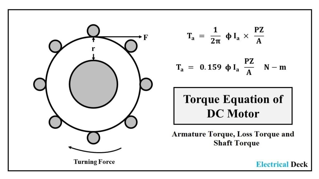
Motor torque is the rotational force the shaft delivers to the load, expressed in newton-meters (Nm) or ounce-inches (oz-in). In a DC motor, torque is produced by the interaction of the magnetic field and the current flowing in the armature windings. The shaft torque at any instant is:
- T = kT · Ia — torque equals the torque constant times the armature current.
- For a permanent-magnet DC (PMDC) motor, kT is set by the magnet flux and the number of effective turns; it is a fixed property until the magnets weaken.
- For a wound-field motor, kT also depends on the field current — a weak field directly lowers torque.
“Losing torque” therefore means one of two things has changed: either kT has dropped (the machine makes less torque per amp) or Ia has dropped (less current is reaching or being used by the armature). Every cause in this article maps to one of those two variables. To understand the parts involved, start with our guide to what a DC motor is and how it is built.
The Two Variables That Decide Torque
| Variable | What changes it | Effect on torque |
|---|---|---|
| kT (torque constant) | Magnet strength, effective turns, field current | Falls with demagnetization or shorted turns → less torque per amp |
| Ia (armature current) | Supply voltage, winding resistance, load, drive limit | Falls with low voltage, high R, overload, or current cap |
How a DC Motor Produces Torque (and Where It Leaks)
A DC motor is a closed electromechanical loop. Follow the chain and you can see exactly where torque is lost:
- Supply applies voltage (Vt) across the brushes or the drive terminals.
- Current (Ia) flows in the armature windings sitting in the magnetic field (B) from the permanent magnets or field coils.
- The Lorentz force (F = B·I·L) on each conductor produces a torque about the shaft.
- The rotor accelerates, and a back-EMF (Eb = kE·ω) builds up, opposing the supply.
- Steady state is reached when Eb ≈ Vt − Ia·Ra, fixing the current and therefore the torque T = kT·Ia.
The governing equations make the leak points obvious:
- Terminal balance: Vt = Eb + Ia·Ra
- Back-EMF: Eb = kE·ω (and in SI units, kE ≈ kT)
- Speed equation: ω = (Vt/kE) − (Ra/kE·kT)·T
Trace the failure modes through these equations:
- Low supply voltage → lower Ia available → lower torque and lower speed.
- Demagnetized magnets → lower kT and kE → less torque per amp, higher speed at no load.
- Hot winding → Ra rises and kT falls → less current and less torque at the same voltage.
- Shorted armature turns → fewer effective turns → lower kT, higher current, more heat.
- Worn bearings / dragging gearbox → load torque rises → Ia climbs until the drive or thermal protection limits it.
Brushed PMDC vs Brushless (BLDC): Where Torque Leaks
Both types use permanent magnets and obey T = kT·Ia, but the failure map differs because commutation is mechanical in one and electronic in the other.
| Cause of torque loss | Brushed PMDC | Brushless PMDC (BLDC) |
|---|---|---|
| Permanent-magnet demagnetization | Yes — over-current / heat | Yes — same physics |
| Brush friction (no-load torque MR) | Yes — wears brushes, raises MR | None (no brushes) |
| Commutation timing | Mechanical off-neutral setting | Electronic — wrong Hall angle (60°/120°) |
| Drive current limit | Simple supply (rarely capped) | PWM current cap — common cause of “weak” torque |
| Winding fault test | Bar-to-bar resistance | Phase-to-phase balance |
For a deeper look at brush wear and sparking, see our guide on why brushed motors spark, and for electronic-commutation trade-offs read BLDC motor disadvantages.
Root-Cause Comparison Table
The table below ranks the seven most common causes by how they attack the torque equation. Use it to triage a motor that feels weak.
| # | Cause | Attacks | Typical symptom | Reversible? |
|---|---|---|---|---|
| 1 | Over-current demagnetization | kT ↓ | High no-load speed, low torque, runs hot under load | No — magnets damaged |
| 2 | Low supply voltage | Ia ↓ | Slow, weak, especially under load | Yes — fix supply |
| 3 | Thermal drift (heat) | kT ↓, Ra ↑ | Torque sags as the motor warms up | Partial — allow cooling |
| 4 | Winding fault (shorted turns) | kT ↓, Ra ↓ | Overheats, high current, low torque | No — rewind/replace |
| 5 | Mechanical overload | Ia capped → T capped | Stalls, trips breaker, high current | Yes — reduce load |
| 6 | Brush / commutator wear | MR ↑, poor contact | Sparking, uneven torque, slow start | Yes — service brushes |
| 7 | Drive / controller limit | Ia capped | Weak only under load, fine unloaded | Yes — raise current limit |
Engineering Data: Torque Formulas & Worked Example
Quantifying torque loss turns guesswork into measurement. These are the relations used by manufacturer datasheets such as FAULHABER and maxon.
| Quantity | Formula | Use in diagnosis |
|---|---|---|
| Torque | T = kT·Ia | Current sets torque; kT is the multiplier |
| Stall (locked-rotor) torque | TLR = (Vt/Ra)·kT | Maximum torque at zero speed (FAULHABER MH) |
| Back-EMF | Eb = kE·ω | Spin test confirms kE = kT (SI) |
| Armature current | Ia = (Vt − Eb)/Ra | Low Vt or high Ra → low Ia |
| Terminal resistance vs temp | R(f) = R(i)·[1 + αcond(θf − θi)] | Copper αcond ≈ +0.004 K−1 (FAULHABER) |
| Torque constant vs temp | k(f) = k(i)·[1 + αmag(θf − θi)] | Magnet αmag ≈ −0.002 K−1 (negative) |
Worked Example: Heat Alone Cuts Torque ~20%
This is taken from a published PMDC thermal analysis (Haydon Kerk Pittman). A 24 V motor has Ra = 0.59 Ω and kT = 0.071 Nm/A at 25 °C. Compare 25 °C to 125 °C:
| Parameter | At 25 °C | At 125 °C | Change |
|---|---|---|---|
| Terminal resistance Ra | 0.59 Ω | 0.83 Ω | +41% |
| Torque constant kT | 0.071 Nm/A | 0.057 Nm/A | −20% |
| Locked-rotor current ILR = Vt/Ra | 40.7 A | 28.9 A | −29% |
| Locked-rotor torque TLR = ILR·kT | 2.89 Nm | 1.65 Nm | −43% |
The takeaway: heat does double damage — it raises winding resistance (less current) and weakens the magnets (less torque per amp). A motor that is fine cold can lose close to half its stall torque once hot. Per IEC 60034-1, winding temperature limits are Class B 130 °C, Class F 155 °C, and Class H 180 °C — exceeding them accelerates permanent demagnetization.
Demagnetization & Armature Reaction (peer-reviewed data)
- Over-current / armature reaction: In a 70 W, 24 V PM BLDC, armature reaction alone reduced peak torque by 2.8% and dropped air-gap flux density by 5.59 mT per amp from no-load to full-load (Upadhyay & Rajagopal, IEEE PEDES 2006). At stall currents (many times rated), the effect is far larger and can become permanent.
- Thermal demagnetization: NdFeB and SmCo magnets have a negative coercive thermal coefficient, so demagnetization risk is highest at maximum operating temperature (ScienceDirect, J. Magn. Magn. Mater., 2020). Once the working point falls below the knee of the B–H curve, magnet flux — and kT — does not recover.
This is why a motor that has been “shorted” or stalled repeatedly loses torque permanently; see our explainer on what happens when you short a DC motor.
Where DC Motor Torque Loss Matters Most
The dominant failure mode tracks the duty cycle and environment. Knowing your application’s main risk shortens diagnosis.
| Application | Dominant torque-loss risk | What to watch |
|---|---|---|
| Automotive (windows, seats, wipers) | Stall / jam → over-current demag | Locked-rotor current vs peak rating |
| Robotics & AGVs | Frequent start-stop, gearbox friction | Gear lubrication, duty-cycle heating |
| Medical & lab instruments | Commutation quality, low noise | Stable kT, clean commutation |
| Power tools & drones | High current, thermal demag | Magnet grade, venting, current limit |
| Conveyors & automation | Sustained overload, heat | Load audit, insulation class |
Robotic joints in particular depend on a reducer to multiply motor torque; a weak motor there cascades into the whole arm — our piece on why robotic arms need speed reducers explains the torque–speed trade.
Selection Guide: How to Spec a DC Motor That Won’t Lose Torque
If diagnosis points to replacement, size the new motor so torque loss never becomes a field complaint.
- Match voltage and type: confirm PMDC, series, shunt, or BLDC, and the supply polarity/range.
- Size torque with margin: select rated torque at least 1.3–1.5× the worst-case load, not the average. Stall/locked-rotor torque must clear the starting load.
- Budget for thermal rise: pick an insulation/magnet class that keeps the winding below IEC 60034-1 limits at your duty cycle; add venting or a larger frame if the motor runs hot.
- Set the drive current limit correctly: for BLDC, set the limit to ~1.2–1.5× rated current for short overload headroom — too low and torque collapses under load.
- Choose magnet grade for temperature: NdFeB for high flux density; verify the knee point stays above your max operating temperature to avoid demag.
- Match the mounting flange: IEC B5/B14 or NEMA C-face so it drops into the existing mount — see our motor flange guide.
Common Engineering Mistakes That Cause Torque Loss
| Mistake | Why it costs torque |
|---|---|
| Exceeding peak / pulse current rating | Permanent magnet demagnetization — kT never recovers |
| Undersized supply or long, thin wires | Voltage drop at the terminals → Ia ↓ → T ↓ (T roughly proportional to V) |
| Ignoring duty-cycle heating | Motor only weak when hot; passes a cold bench test |
| Wrong Hall angle (60° vs 120°) on BLDC | Incorrect commutation timing → weak starting torque |
| Over- or under-lubricating a gearmotor | Grease drag raises load torque and wastes shaft output |
| Reading inrush current as a fault | Stall current Vt/Ra is normal at start; masking the real issue |
| Sizing by rated torque only | No margin for starting/overload → chronic “weak” feel |
DC Motor Torque-Loss Troubleshooting Table (Problem → Cause → Solution)
| Problem | Likely Cause | Solution |
|---|---|---|
| Weak or no torque at start | Low supply V, demagnetized magnets, open winding, seized bearing | Measure Vt at terminals; check magnet kT; test winding R; free the shaft |
| Torque drops only as it warms up | Thermal drift: Ra ↑, kT ↓ | Allow cooling; reduce duty; upgrade insulation/magnet class |
| Weak only under load, fine unloaded | Drive current limit too low, or genuine overload | Raise current limit to 1.2–1.5× rated; reduce load |
| High no-load speed but low torque | Permanent demagnetization | Confirm via back-EMF / kT test vs nameplate; replace magnets or motor |
| Intermittent weak torque | Loose connection, thermal trip, dirty commutator | Tighten terminals; check current limit; clean/resurface commutator |
| Torque decays over months | Gradual demag, bearing wear, brush loss | Replace brushes/bearings; re-lubricate; re-magnetize or replace |
| New motor is weak out of the box | Wrong part number, wrong Hall angle, bad drive setting | Verify spec; set 60°/120°; match drive parameters |
For the full diagnostic sequence (including insulation and back-EMF tests), use our DC motor troubleshooting guide.
Frequently Asked Questions
Does low voltage reduce DC motor torque?
Yes. Torque follows T ≈ kT·(Vt − Eb)/Ra, so a lower terminal voltage means less armature current and therefore less torque. A motor on a weak supply or long, thin wiring will feel sluggish and slow, especially under load, because the voltage at the terminals drops under current draw.
Can a DC motor lose torque permanently?
Yes — if the permanent magnets are demagnetized by sustained over-current or excessive heat, the torque constant kT drops and does not recover. The only fixes are re-magnetizing the magnets (rarely practical) or replacing the rotor/motor. This is why peak and stall currents must stay within the nameplate rating.
How much torque does heat cost a DC motor?
Substantial. In a documented 24 V PMDC, raising the winding temperature from 25 °C to 125 °C cut the torque constant about 20% and locked-rotor torque from ~2.9 Nm to ~1.65 Nm — roughly a 43% loss of stall torque. Heat raises winding resistance and weakens the magnets at the same time.
Why does my BLDC lose torque after a stall?
Stall current equals Vt/Ra and can be many times the rated value. Sustained stall overheats the windings and demagnetizes the magnets, and most BLDC drives also impose a current limit that caps torque. Repeated stalling is the fastest route to permanent torque loss.
How do I test a DC motor for demagnetization?
Compare its actual performance to the nameplate: a demagnetized motor shows high no-load speed with low torque, and a reduced back-EMF constant (spin it as a generator and measure V per 1000 RPM) and reduced torque constant kT. A megger test (IEEE 43) checks the winding; demag is confirmed by the torque/back-EMF drop, not by insulation.
Is torque loss different in brushed vs brushless DC motors?
The magnet physics (T = kT·Ia) is identical, but brushed motors also lose torque through brush friction and commutator wear, while brushless motors lose it through drive current limits and Hall-sensor/timing errors. A brushed motor’s torque loss is usually mechanical and repairable; a BLDC’s is often in the controller settings.
Why Choose Greensky for DC & Motion Replacement Motors?
When torque loss points to replacement rather than repair, Greensky supplies a complete DC portfolio — PMDC, brushed, and brushless (BLDC) motors plus integrated gear motors — built to IEC 60034 and NEMA MG 1 dimensions so they drop into existing mounts. For maintenance and procurement teams we provide:
- Documented torque constants: nameplate kT, stall torque, rated current and insulation class so your baseline is clear from day one.
- Thermal headroom: Class F and H insulation options and magnet grades selected for your duty-cycle temperature, not just the catalog average.
- Flange compatibility: IEC B5/B14 and NEMA C-face with customized pilot diameters — see our motor flange guide.
- Brushed or BLDC: choose mechanical simplicity or electronic commutation with matched Hall sensors and drives.
- Low-MOQ OEM/ODM: small batches for spares programs and custom shaft/encoder configurations.
Related Reading
- What Is a DC Motor? Types, Principle & Formulas
- How to Troubleshoot a DC Motor: Step-by-Step Guide
- Why Do Brushed Motors Spark? Causes & Fixes
- How to Short a DC Motor (Short-Circuit Braking)
- BLDC Motor Disadvantages Engineers Should Know
- What Is a Motor Flange? IEC vs NEMA Mounting
- AC vs DC Motor: Which to Choose
- Gearbox vs Gear Motor: Differences & Selection
- Synchronous vs Induction Motor: Key Differences
- Why Robotic Arms Need Speed Reducers
References
- IEC 60034-1 — Rotating Electrical Machines: Rating and Performance (temperature classes, torque definitions). webstore.iec.ch/publication/67467
- IEC 60034-30-1 — Efficiency Classes for Rotating Electrical Machines (IE1–IE5). webstore.iec.ch/publication/67784
- NEMA MG 1 — Motors and Generators (safety, thermal, mounting dimensions). nema.org/standards/view/mg-1-motors-and-generators
- IEEE 43-2013 — Recommended Practice for Insulation Resistance Testing of Rotating Machinery. standards.ieee.org/ieee/43/4385
- IEEE 112 — Standard Test Procedure for Polyphase Induction & DC Motors (loss & back-EMF methods). standards.ieee.org/ieee/112/4213
- U.S. DOE — Electric Motor Efficiency Determination & Repair Guidance. energy.gov/eere/amo/articles/determination-electric-motors
- SKF — Bearing maintenance and lubrication for electric motors. skf.com/us/products/maintenance-products/bearing-maintenance
- Haydon Kerk Pittman — Temperature Effects on DC Motor Performance (thermal torque-constant model). haydonkerkpittman.com/learningzone/whitepapers/temperature-effects-on-dc-motor-performance
- FAULHABER — DC-Motors Technical Information (kM, kE, α coefficients, stall torque). faulhaber.com/en/technical-information
- maxon — DC motor commutation and application notes. maxon.com/en-us/technologies/tech-papers
